Installation Guide for TRIKDIS Communicator + DSC alarm system control panel
- 19.01.2024

This installation guide aims to assist in the installation of TRIKDIS E16, G16, and GET smart communicators. The guide provides step-by-step instructions for compatible DSC alarm system control panels.
The guide primarily aims to help create the alarm system control panel in the free Protegus 2 user application. As a result, the events of the alarm system become visible in the app, and in many cases, there is also the possibility to control the alarm (arming/disarming).
Attention!
Electricity can be dangerous and may cause personal injury or DEATH, as well as other financial loss or damage if not used or installed properly.
Installation involves working with electrical equipment, and it should be executed in accordance with current regulations!
Warranty validation requires the device to be installed by a qualified person following the installation regulations for electrical equipment and adhering to the current regulations for the safe operation of electrical equipment.
Which DSC alarm system control panel can be used with this guide?
The description only applies to DSC alarm system control panels found in the table below.
Alarm panels connectable via data bus or serial port
The Trikdis E16, G16, and GET can be used with all alarm panels listed below. The great benefit using the special Trikdis communicators, that events are received via the data bus or serial port.
Control panels marked red can be controlled directly from the serial port / data bus without any further wiring.
Control panels marked black means these control panels get the events from the serial port / data bus, but for remotely controlling the alarm system, key-switch zones and additional wiring is required
Magellan MG5000, MG5050, MG5050+*, MG5050E
DIGIPLEX EVO48, NE96, EVO96, EVO192*, EVOHD* (*Fw. 7.50 or above)
ESPRIT E55, 728ULT, 738ULT
Firmware PARADOX control panels, which are directly controlled, must be V.4 or higher.
* The serial port on the marked NEW alarm panels is factory-locked. Serial port unlocking must be performed to communicate with any external devices. How to unlock Serial Port
Premier Elite 12, 24, 48, 64, 88, 168
Are you looking for an universal communicator?
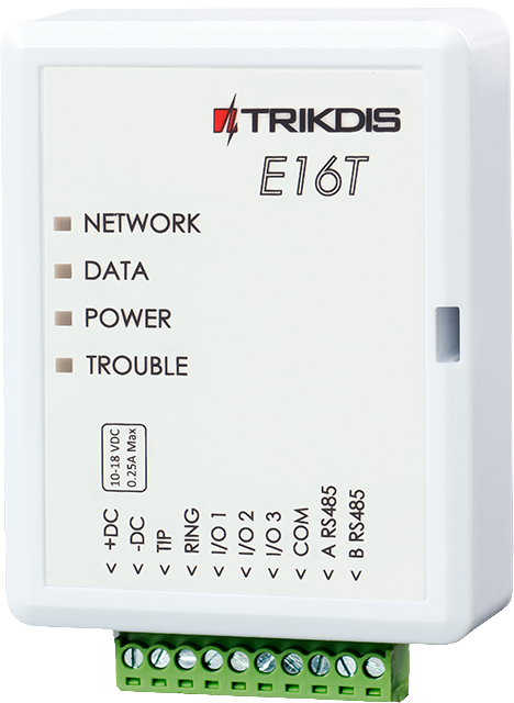
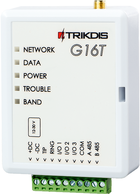
Tridis E16T Ethernet and G16T cellular communicator can be used with any manufacturers control panel with telephone line (TIP RING) connection and Contact ID format. As a result you can see all events from your control panel and even remotely control the partitions using keyswitch zones in the free Protegus 2 app.
The guide consists of the following chapters.
- Wiring between the DSC alarm system control panel and the communicator
- Programming the TRIKDIS communicator
- Starting the TRIKDIS communicator
- Creating the system in the Protegus 2 application
Wiring between the DSC alarm system control panel and the communicator
Warining!
It is forbidden to perform wiring on a device under voltage. Before starting the work, disconnect power (including backup batteries).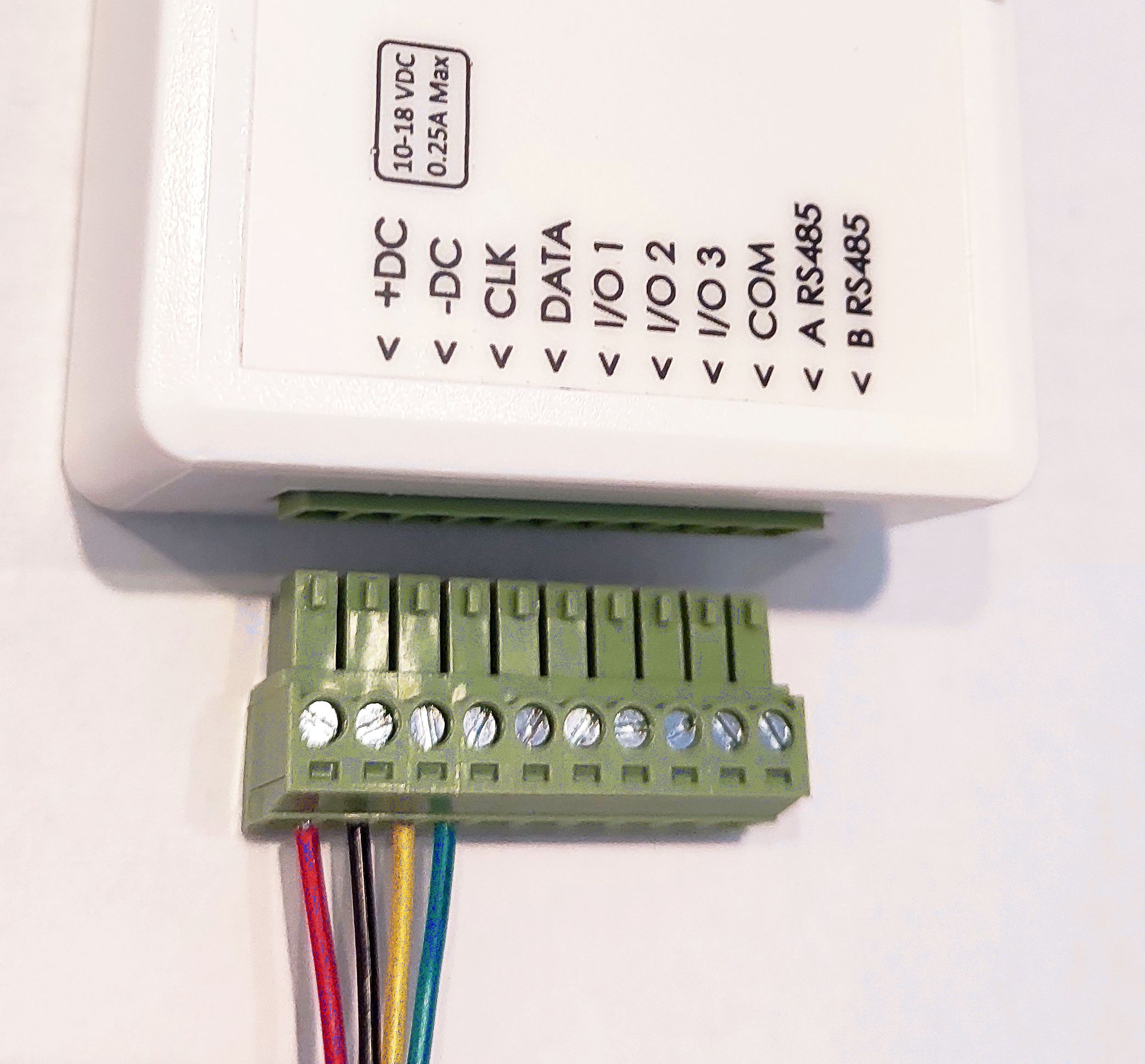
Detachable Terminal Block
In many cases, it is very useful that the terminal block at the bottom of the device can be removed:
- It allows the device to be turned off or restarted with a single motion.
- Easier more convenient wiring.
- The Trikdis device can be brought to the computer for programming with a USB cable.
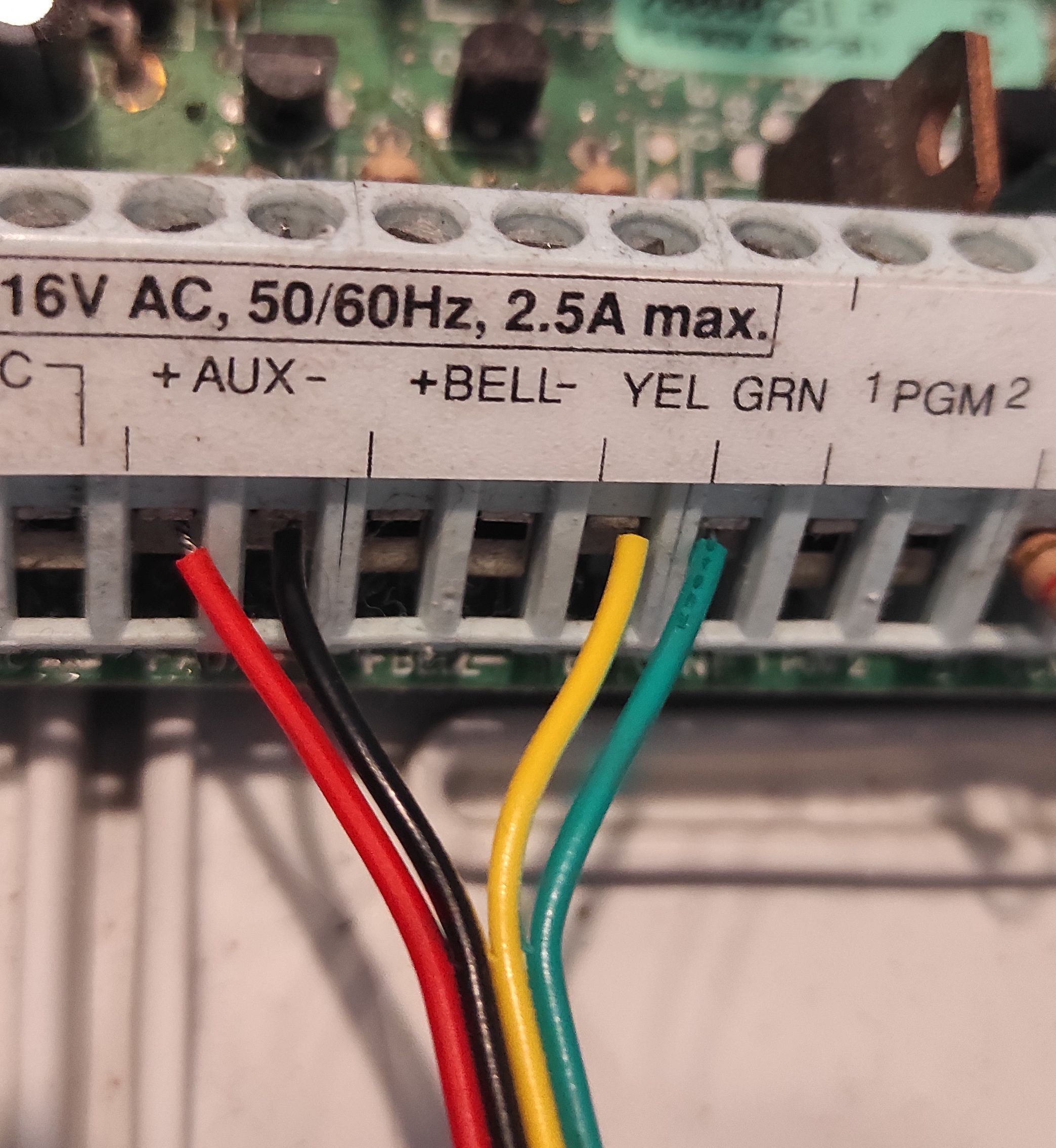
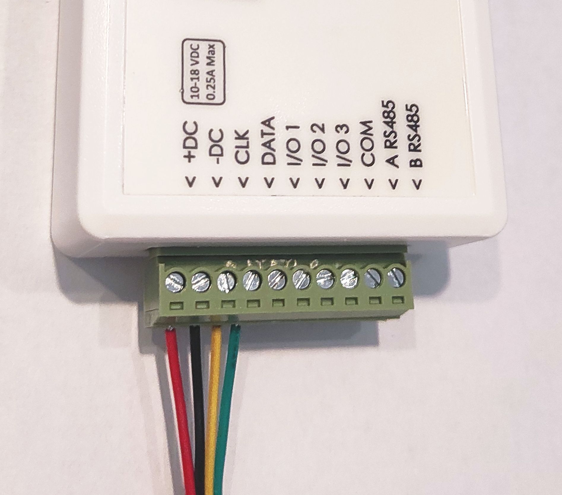
To connect the DSC panel and the TRIKDIS communicator, you will need at least a four-core alarm cable. The wiring must be done as shown in the table below.
| TRIKDIS communicator | DSC alarm system control panel | Typical wire color coding |
| +DC | AUX+ | Red |
| -DC | AUX- | Black |
| Clk | YEL | Yellow |
| Data | GREEN | Green |
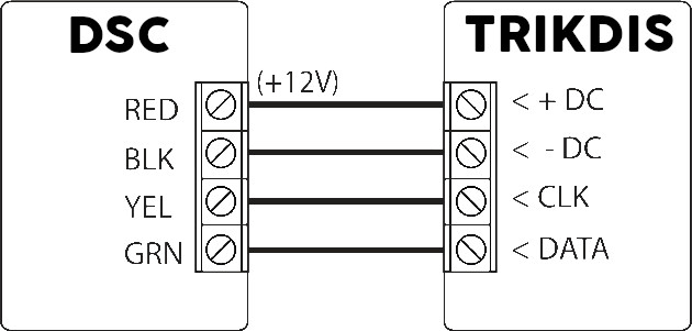
Connection of DSC and Trikdis device via data bus
Programming the TRIKDIS communicator
All Trikdis devices can be programmed using a common software. The software is called TrikdisConfig and can be downloaded from the manufacturer's website.
After downloading, install the program. If a new version is available each time you start TrikdisConfig, download and install the recommended update!
- Connect the computer and the TRIKDIS communicator with a mini-USB cable. (For GET, a USB-C cable is required)
- Read the device settings.
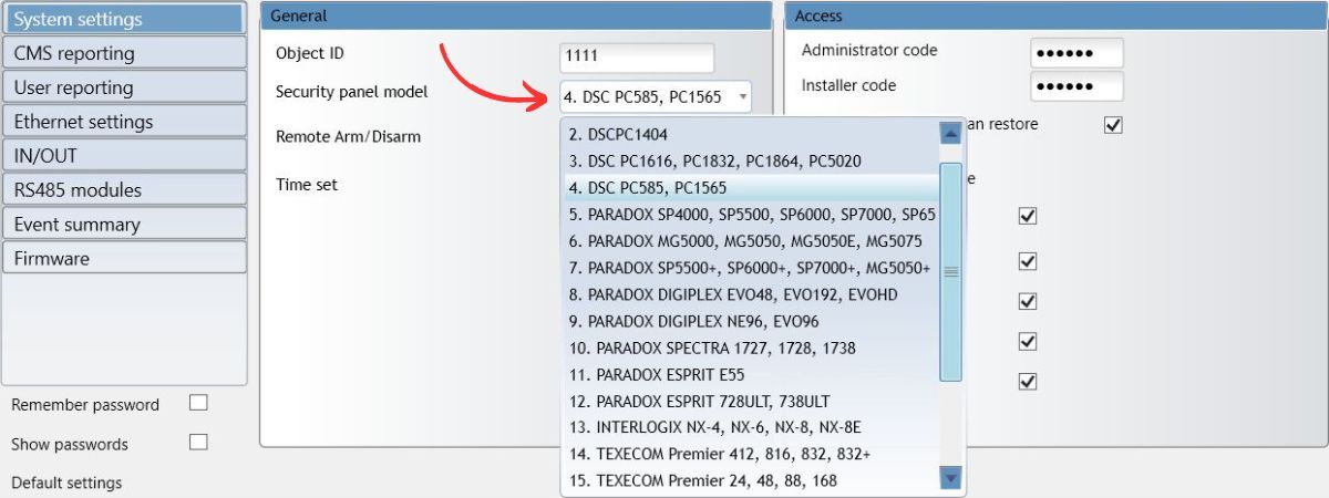
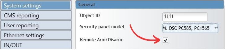
- In System Settings > General tab, select the Alarm system control panel type from the dropdown menu that corresponds to the panel connected to the TRIKDIS communicator.
- The direct control (remote arming / disarming) can only be enabled if the selected panel supports this feature (highlighted in red in the list above).
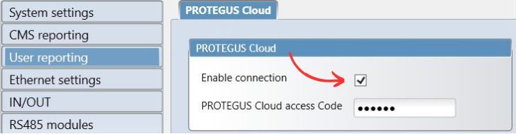
- In the User Reporting tab, check the enable the connection and choose a six-digit numeric connection password.
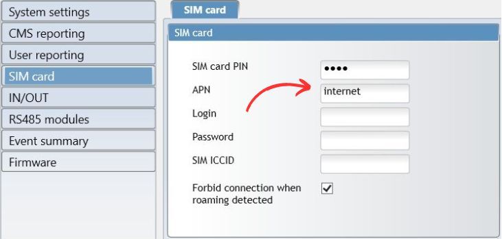
- Make the necessary settings for internet access
- Ethernet settings are only needed if the network device does not allocate an automatic IP address (e.g., router).
- For SIM card devices, the correct APN setting is required for data connection.
- It is recommended to disable the use of PIN codes on a phone before inserting the SIM card into the TRIKDIS device. If you still want to use the PIN code, be sure to enter it.

- write the settings into the device.
- After successful writing, you can unplug the USB cable from the TRIKDIS device.
Starting the TRIKDIS communicator
- For SIM card communicators, insert the SIM card into the device before starting.
- For devices with Ethernet, you can connect the Ethernet cable before or after starting up.
- For startup, unplug the USB cable and connect the pulled jumper.
You can proceed to the next chapter when the device starts correctly and does not indicate any errors.
- The Power LED is green
- The Trouble LED does not flash red
- The Network LED is green (if it flashes yellow, it is okay)
- If the Data LED does not turn off, it means that the device cannot send some event. This indicates an internet / data connection error.
Creating the system in the Protegus 2 application
- Download the Protegus 2 application to your phone or open it in a browser
- Register an account if you haven't already.
- Log into your account.
- On the main page, click the "+" button to create a system
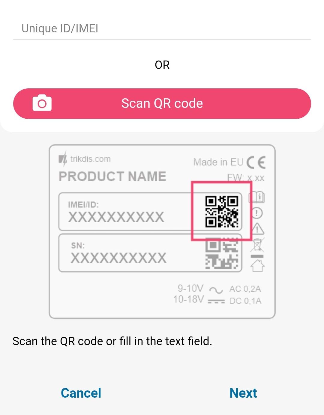
- Enter the unique identifier of the TRIKDIS device (you can also scan the barcode or QR code with your phone's camera), which you can find
- On the sticker of the device
- On the device's cardboard box
- In the bottom left corner of TrikdisConfig (selectable and copyable format)
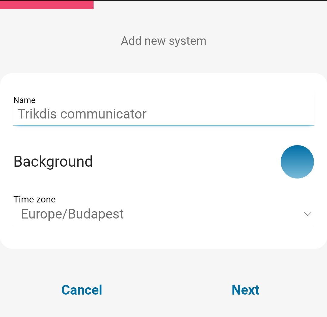
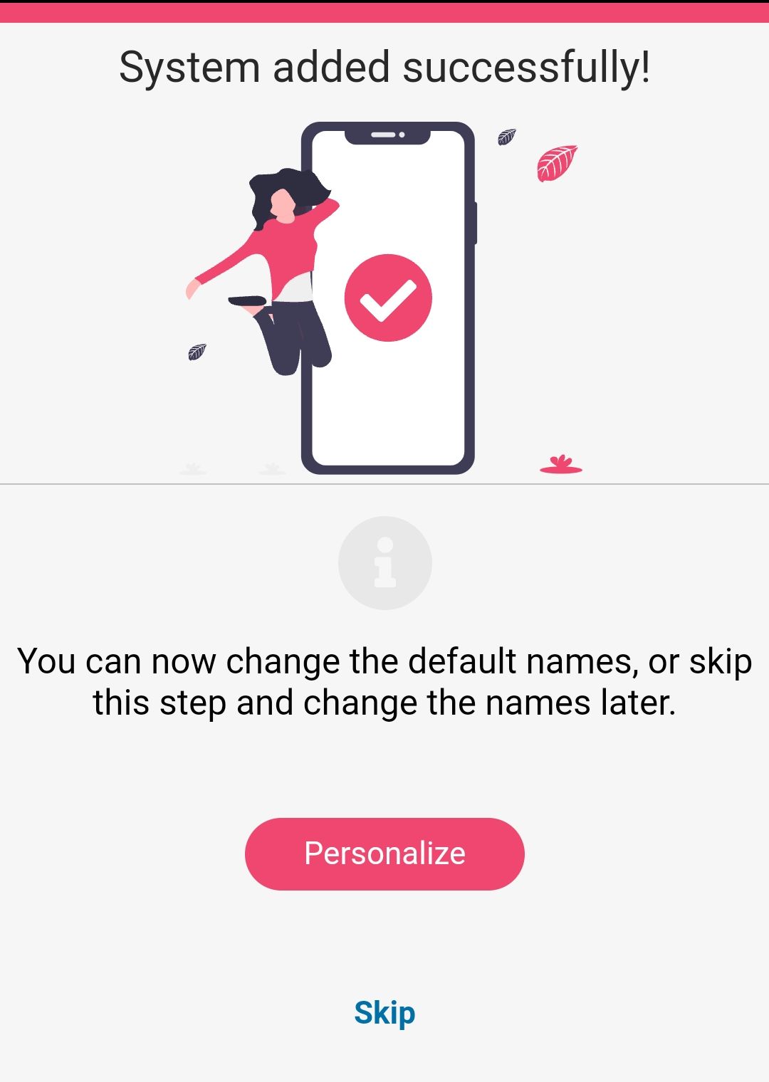
- Enter the system name and select a time zone
- Your system is created, you can still name the partitions and zones at the next step, but you can do this later anytime.
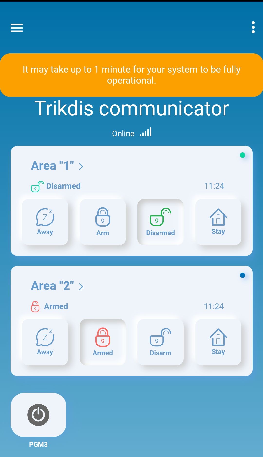
- In the last step, your system's home screen will appear. Wait until the yellow stripe disappears and your system is ready.

Tags:
Related Products

Trikdis G16 2G GSM smart communicator
The G16 2G GSM smart communicator can cooperate with Paradox, DSC, and other manufacturers' alarm sy..
€118.90 Ex Tax: €99.08

Trikdis E16 Ethernet Communicator - IP module
The Trikdis E16 Ethernet communicator can cooperate with Paradox, DSC, and other alarm panels by com..
€84.90 Ex Tax: €70.75

Trikdis GET Ethernet + 4G smart communicator
The Trikdis GET Ethernet + 4G smart communicator is the top-tier device from the manufacturer, combi..
€239.90 Ex Tax: €199.92

Trikdis G16 4G GSM smart communicator
The G16 4G GSM smart communicator can cooperate with Paradox, DSC, and other manufacturers' alarm sy..
€172.90 Ex Tax: €144.08